datetime:2023/11/02 10:06
author:nzb
该项目来源于大佬的动手学ROS2
11.两轮差速机器人运动学介绍
一、两轮差速运动学模型
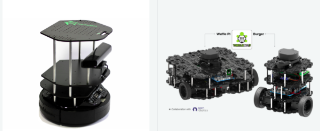
两轮差速模型指机器人底盘由两个驱动轮和若干支撑轮构成的底盘模型,像turtlebot和开源机器人fishbot都是两轮差速模型。
两轮差速模型通过两个驱动轮可以通过不同转速和转向,使得机器人的达到某个特定的角速度和线速度。
二、正逆解
了解了两轮差速模型,那正逆解又是怎么回事?
正运动学:已知两个轮子的速度,求整车的角速度(弧度/秒)和线速度(米/秒)
逆运动学:已知目标角速度和线速度,求两个轮子的转速
三、轮式里程计
当我们知道了两个轮子之间的相对位置,同时知道了每一时刻机器人的角速度和线速度,那我们如何获取机器人的当前角度和位置呢?
3.1 角度
影响机器人当前角度的因素只有一个,就是角速度。
某一时刻机器人转动的角度 = 这一时刻机器人的角速度*这一时刻时长
假如我们认定初始时刻机器人的角度为0,通过对机器人转动角度角度进行累加,即可获得机器人的当前角度。
上述过程其实就是对角速度进行积分得到角度。
3.2 位置
通过对角速度积分,我们得到了角度。
机器人某一时刻自身方向上的前进速度可以分解为里程计坐标系中x轴和y轴方向上的速度。
从图中可以看出:
得到了x和y方向上的速度,乘上该速度对应的某一时刻经过的时间,即可得到这一时刻在x轴和y轴方向上的位移,对位移进行累加即可得到里程计中的x和y。
12. 实时速度计算-运动学正解
上一节了解了两轮差速运动学,本节我们线进一步的了解两轮差速正运动学的推导过程,并利用两轮差速运动学正解,来完成对小车的实时速度计算。
一、正运动学解推导
两轮差速机器人是一种常见的移动机器人类型,由两个轮子和一个中心点组成。我们可以通过控制每个轮子的转速来实现移动,并且可以在一个平面上进行自由移动。
前面章节我们通过PID+编码器完成了FishBot底盘两个轮子单独速度的测量,但是在实际使用当中,我们把机器人当作一个整体来看,而对于这样一个整体在空间中的速度,我们一般采用X轴线速度 和Z轴角速度 来描述。
需要注意的是:在ROS中,机器人的前方通常指的是机器人本体坐标系的正方向。本体坐标系是相对于机器人自身的一个坐标系,通常定义在机器人的中心位置,以机器人的前进方向为X轴,左侧为Y轴,垂直于机器人平面的方向为Z轴。
而全局坐标系中的正方向X轴指向右方,Y轴指向前方,Z轴垂直于地面。
X Y Z 机器人本体坐标系 前方 左侧 垂直于机器人平面 全局坐标系 右方 前方 垂直于地面
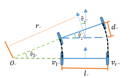
所以问题就变成了假设机器人在一小段时间内,它的左右轮子线速度和保持不变 ,两轮之间的安装间距,求机器人的线速度 ,角速度。
我们看上图来推导
因为机器人的线速度方向和轮子转动方向始终保持一致,所以机器人的线速度为做右轮线速度的平均值,即:
我们知道
根据上图所以有
同一个机器人角速度相同,所以有
可以求出
二、正运动学代码实现
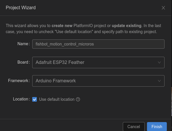
2.1 新建工程
从本节开始我们持续的在一个工程上进行开发,推荐大家建立代码仓库,并将代码用git进行管理起来。
在PlatformIO上新建fishbot_motion_control_microros工程。
添加依赖
[env:featheresp32]
platform = espressif32
board = featheresp32
framework = arduino
board_microros_transport = wifi
board_microros_distro = humble
board_build.f_cpu = 240000000L
board_build.f_flash = 80000000L
monitor_speed = 115200
lib_deps =
    https://gitee.com/ohhuo/micro_ros_platformio.git
    https://github.com/fishros/Esp32McpwmMotor.git
    https://github.com/fishros/Esp32PcntEncoder.git
接着将前面章节中pid_controller样例程序的lib下的内容和main.cpp内容复制过来,最终就目录结构如下:
.
├── include
│   └── README
├── lib
│   ├── PidController
│   │   ├── PidController.cpp
│   │   └── PidController.h
│   └── README
├── LICENSE
├── platformio.ini
├── src
│   └── main.cpp
└── test
    ├── my_main.cpp
    ├── README
2.2 添加Kinematic库
在lib下添加Kinematics文件夹,并添加Kinematics.h和Kinematics.cpp文件。
编写Kinematics.h
/**
 * @file Kinematics.h
 * @author fishros@foxmail.com
 * @brief 机器人模型设置,编码器轮速转换,ODOM推算,线速度角速度分解
 * @version V1.0.0
 * @date 2022-12-10
 *
 * @copyright Copyright www.fishros.com (c) 2022
 *
 */
#ifndef __KINEMATICS_H__
#define __KINEMATICS_H__
#include <Arduino.h>

typedef struct
{
    uint8_t id;                // 电机编号
    uint16_t reducation_ratio; // 减速器减速比,轮子转一圈,电机需要转的圈数
    uint16_t pulse_ration;     // 脉冲比,电机转一圈所产生的脉冲数
    float wheel_diameter;      // 轮子的外直径,单位mm

    float per_pulse_distance;  // 无需配置,单个脉冲轮子前进的距离,单位mm,设置时自动计算
                               // 单个脉冲距离=轮子转一圈所行进的距离/轮子转一圈所产生的脉冲数
                               // per_pulse_distance= (wheel_diameter*3.1415926)/(pulse_ration*reducation_ratio)
    uint32_t speed_factor;     // 无需配置,计算速度时使用的速度因子,设置时自动计算,speed_factor计算方式如下
                               // 设 dt(单位us,1s=1000ms=10^6us)时间内的脉冲数为dtick
                               // 速度speed = per_pulse_distance*dtick/(dt/1000/1000)=(per_pulse_distance*1000*1000)*dtick/dt
                               // 记 speed_factor = (per_pulse_distance*1000*1000)
    int16_t motor_speed;       // 无需配置,当前电机速度mm/s,计算时使用
    int64_t last_encoder_tick; // 无需配置,上次电机的编码器读数
    uint64_t last_update_time; // 无需配置,上次更新数据的时间,单位us
} motor_param_t;


class Kinematics
{
private:
    motor_param_t motor_param_[2];
    float wheel_distance_; // 轮子间距
public:
    Kinematics(/* args */) = default;
    ~Kinematics() = default;

    /**
     * @brief 设置电机相关参数
     *
     * @param id
     * @param reducation_ratio
     * @param pulse_ration
     * @param wheel_diameter
     */
    void set_motor_param(uint8_t id, uint16_t reducation_ratio, uint16_t pulse_ration, float wheel_diameter);
    /**
     * @brief 设置运动学相关参数
     *
     * @param wheel_distance
     */
    void set_kinematic_param(float wheel_distance);

    /**
     * @brief 运动学逆解,输入机器人当前线速度和角速度,输出左右轮子应该达到的目标速度
     *
     * @param line_speed
     * @param angle_speed
     * @param out_wheel1_speed
     * @param out_wheel2_speed
     */
    void kinematic_inverse(float line_speed, float angle_speed, float &out_wheel1_speed, float &out_wheel2_speed);


    /**
     * @brief 运动学正解,输入左右轮子速度,输出机器人当前线速度和角速度
     *
     * @param wheel1_speed
     * @param wheel2_speed
     * @param line_speed
     * @param angle_speed
     */
    void kinematic_forward(float wheel1_speed, float wheel2_speed, float &line_speed, float &angle_speed);

    /**
     * @brief 更新轮子的tick数据
     *
     * @param current_time
     * @param motor_tick1
     * @param motor_tick2
     */
    void update_motor_ticks(uint64_t current_time, int32_t motor_tick1, int32_t motor_tick2);

    /**
     * @brief 获取轮子当前速度
     *
     * @param id
     * @return float
     */
    float motor_speed(uint8_t id);
};

#endif // __KINEMATICS_H__
这里主要定义了一个电机参数结构体,并定义了一个类,该类包含以下6个函数
| 函数名称 | 描述 |
|---|---|
set_motor_param() |
设置电机相关参数 |
set_kinematic_param() |
设置运动学相关参数 |
kinematic_inverse() |
运动学逆解,输入机器人当前线速度和角速度,输出左右轮子应该达到的目标速度 |
kinematic_forward() |
运动学正解,输入左右轮子速度,输出机器人当前线速度和角速度 |
update_motor_ticks() |
更新轮子的tick数据 |
motor_speed() |
获取轮子当前速度 |
2.3 Kinematics.cpp代码实现
#include "Kinematics.h"

void Kinematics::set_motor_param(uint8_t id, uint16_t reducation_ratio, uint16_t pulse_ration, float wheel_diameter)
{
    motor_param_[id].id = id;   // 设置电机ID
    motor_param_[id].reducation_ratio = reducation_ratio;   // 设置减速比
    motor_param_[id].pulse_ration = pulse_ration;   // 设置脉冲比
    motor_param_[id].wheel_diameter = wheel_diameter;   // 设置车轮直径
    motor_param_[id].per_pulse_distance = (wheel_diameter * PI) / (reducation_ratio * pulse_ration);   // 每个脉冲对应行驶距离
    motor_param_[id].speed_factor = (1000 * 1000) * (wheel_diameter * PI) / (reducation_ratio * pulse_ration);   // 计算速度因子
    Serial.printf("init motor param %d: %f=%f*PI/(%d*%d) speed_factor=%d\n", id, motor_param_[id].per_pulse_distance, wheel_diameter, reducation_ratio, pulse_ration, motor_param_[id].speed_factor);   // 打印调试信息
}

void Kinematics::set_kinematic_param(float wheel_distance)
{
    wheel_distance_ = wheel_distance;   // 设置轮间距离
}

void Kinematics::update_motor_ticks(uint64_t current_time, int32_t motor_tick1, int32_t motor_tick2)
{

    uint32_t dt = current_time - motor_param_[0].last_update_time;   // 计算时间差
    int32_t dtick1 = motor_tick1 - motor_param_[0].last_encoder_tick;   // 计算电机1脉冲差
    int32_t dtick2 = motor_tick2 - motor_param_[1].last_encoder_tick;   // 计算电机2脉冲差
    // 轮子速度计算
    motor_param_[0].motor_speed = dtick1 * (motor_param_[0].speed_factor / dt);   // 计算电机1轮子速度
    motor_param_[1].motor_speed = dtick2 * (motor_param_[1].speed_factor / dt);   // 计算电机2轮子速度

    motor_param_[0].last_encoder_tick = motor_tick1;   // 更新电机1上一次的脉冲计数
    motor_param_[1].last_encoder_tick = motor_tick2;   // 更新电机2上一次的脉冲计数
    motor_param_[0].last_update_time = current_time;   // 更新电机1上一次更新时间
    motor_param_[1].last_update_time = current_time;   // 更新电机2上一次更新时间
}

void Kinematics::kinematic_inverse(float linear_speed, float angular_speed, float &out_wheel1_speed, float &out_wheel2_speed)
{
}

void Kinematics::kinematic_forward(float wheel1_speed, float wheel2_speed, float &linear_speed, float &angular_speed)
{
    linear_speed = (wheel1_speed + wheel2_speed) / 2.0;   // 计算线速度
    angular_speed = (wheel2_speed - wheel1_speed) / wheel_distance_;   // 计算角速度
}

float Kinematics::motor_speed(uint8_t id)
{
    return motor_param_[id].motor_speed; // 返回指定id的轮子速度
}
2.4 修改main.cpp
#include <Arduino.h>
#include <micro_ros_platformio.h>    // 包含用于 ESP32 的 micro-ROS PlatformIO 库
#include <WiFi.h>                    // 包含 ESP32 的 WiFi 库
#include <rcl/rcl.h>                 // 包含 ROS 客户端库 (RCL)
#include <rclc/rclc.h>               // 包含用于 C 的 ROS 客户端库 (RCLC)
#include <rclc/executor.h>           // 包含 RCLC 执行程序库,用于执行订阅和发布
#include <geometry_msgs/msg/twist.h> // 包含 ROS2 geometry_msgs/Twist 消息类型
#include <Esp32PcntEncoder.h>        // 包含用于计数电机编码器脉冲的 ESP32 PCNT 编码器库
#include <Esp32McpwmMotor.h>         // 包含使用 ESP32 的 MCPWM 硬件模块控制 DC 电机的 ESP32 MCPWM 电机库
#include <PidController.h>           // 包含 PID 控制器库,用于实现 PID 控制
#include <Kinematics.h>              // 运动学相关实现

Esp32PcntEncoder encoders[2];      // 创建一个长度为 2 的 ESP32 PCNT 编码器数组
rclc_executor_t executor;          // 创建一个 RCLC 执行程序对象,用于处理订阅和发布
rclc_support_t support;            // 创建一个 RCLC 支持对象,用于管理 ROS2 上下文和节点
rcl_allocator_t allocator;         // 创建一个 RCL 分配器对象,用于分配内存
rcl_node_t node;                   // 创建一个 RCL 节点对象,用于此基于 ESP32 的机器人小车
rcl_subscription_t subscriber;     // 创建一个 RCL 订阅对象,用于订阅 ROS2 消息
geometry_msgs__msg__Twist sub_msg; // 创建一个 ROS2 geometry_msgs/Twist 消息对象
Esp32McpwmMotor motor;             // 创建一个 ESP32 MCPWM 电机对象,用于控制 DC 电机

float out_motor_speed[2];        // 创建一个长度为 2 的浮点数数组,用于保存输出电机速度
PidController pid_controller[2]; // 创建PidController的两个对象
Kinematics kinematics;           // 运动学相关对象

void twist_callback(const void *msg_in)
{
  const geometry_msgs__msg__Twist *twist_msg = (const geometry_msgs__msg__Twist *)msg_in;
  static float target_motor_speed1, target_motor_speed2;
  float linear_x = twist_msg->linear.x;   // 获取 Twist 消息的线性 x 分量
  float angular_z = twist_msg->angular.z; // 获取 Twist 消息的角度 z 分量
  kinematics.kinematic_inverse(linear_x * 1000, angular_z, target_motor_speed1, target_motor_speed2);
  pid_controller[0].update_target(target_motor_speed1);
  pid_controller[1].update_target(target_motor_speed2);
}

// 这个函数是一个后台任务,负责设置和处理与 micro-ROS 代理的通信。
void microros_task(void *param)
{
  // 设置 micro-ROS 代理的 IP 地址。
  IPAddress agent_ip;
  agent_ip.fromString("192.168.2.105");

  // 使用 WiFi 网络和代理 IP 设置 micro-ROS 传输层。
  set_microros_wifi_transports("fishbot", "12345678", agent_ip, 8888);

  // 等待 2 秒,以便网络连接得到建立。
  delay(2000);

  // 设置 micro-ROS 支持结构、节点和订阅。
  allocator = rcl_get_default_allocator();
  rclc_support_init(&support, 0, NULL, &allocator);
  rclc_node_init_default(&node, "esp32_car", "", &support);
  rclc_subscription_init_default(
      &subscriber,
      &node,
      ROSIDL_GET_MSG_TYPE_SUPPORT(geometry_msgs, msg, Twist),
      "/cmd_vel");

  // 设置 micro-ROS 执行器,并将订阅添加到其中。
  rclc_executor_init(&executor, &support.context, 1, &allocator);
  rclc_executor_add_subscription(&executor, &subscriber, &sub_msg, &twist_callback, ON_NEW_DATA);

  // 循环运行 micro-ROS 执行器以处理传入的消息。
  while (true)
  {
    delay(100);
    rclc_executor_spin_some(&executor, RCL_MS_TO_NS(100));
  }
}


void setup()
{
  // 初始化串口通信,波特率为115200
  Serial.begin(115200);
  // 将两个电机分别连接到引脚22、23和12、13上
  motor.attachMotor(0, 22, 23);
  motor.attachMotor(1, 12, 13);
  // 在引脚32、33和26、25上初始化两个编码器
  encoders[0].init(0, 32, 33);
  encoders[1].init(1, 26, 25);
  // 初始化PID控制器的kp、ki和kd
  pid_controller[0].update_pid(0.625, 0.125, 0.0);
  pid_controller[1].update_pid(0.625, 0.125, 0.0);
  // 初始化PID控制器的最大输入输出,MPCNT大小范围在正负100之间
  pid_controller[0].out_limit(-100, 100);
  pid_controller[1].out_limit(-100, 100);

  // 设置运动学参数
  kinematics.set_motor_param(0, 45, 44, 65);
  kinematics.set_motor_param(1, 45, 44, 65);
  kinematics.set_kinematic_param(150);

  // 在核心0上创建一个名为"microros_task"的任务,栈大小为10240
  xTaskCreatePinnedToCore(microros_task, "microros_task", 10240, NULL, 1, NULL, 0);
}

void loop()
{
  static float out_motor_speed[2];
  static uint64_t last_update_info_time = millis();
  kinematics.update_motor_ticks(micros(), encoders[0].getTicks(), encoders[1].getTicks());
  out_motor_speed[0] = pid_controller[0].update(kinematics.motor_speed(0));
  out_motor_speed[1] = pid_controller[1].update(kinematics.motor_speed(1));
  motor.updateMotorSpeed(0, out_motor_speed[0]);
  motor.updateMotorSpeed(1, out_motor_speed[1]);
  // 延迟10毫秒
  delay(10);
}
这里主要调用Kinematic完成相关函数的调用。
主要有下面几行
// 初始化运动学相关对象
Kinematics kinematics;
// 设置运动学参数
kinematics.set_motor_param(0, 45, 44, 65);
kinematics.set_motor_param(1, 45, 44, 65);
kinematics.set_kinematic_param(150);
// 更新电机速度
kinematics.update_motor_ticks(micros(), encoders[0].getTicks(), encoders[1].getTicks());
// 运动学逆解
kinematics.kinematic_inverse(linear_x * 1000, angular_z, target_motor_speed1, target_motor_speed2);
三、上传测试
下载代码,运行agent,点击RST按键。
sudo docker run -it --rm -v /dev:/dev -v /dev/shm:/dev/shm --privileged --net=host microros/micro-ros-agent:$ROS_DISTRO udp4 --port 8888 -v6
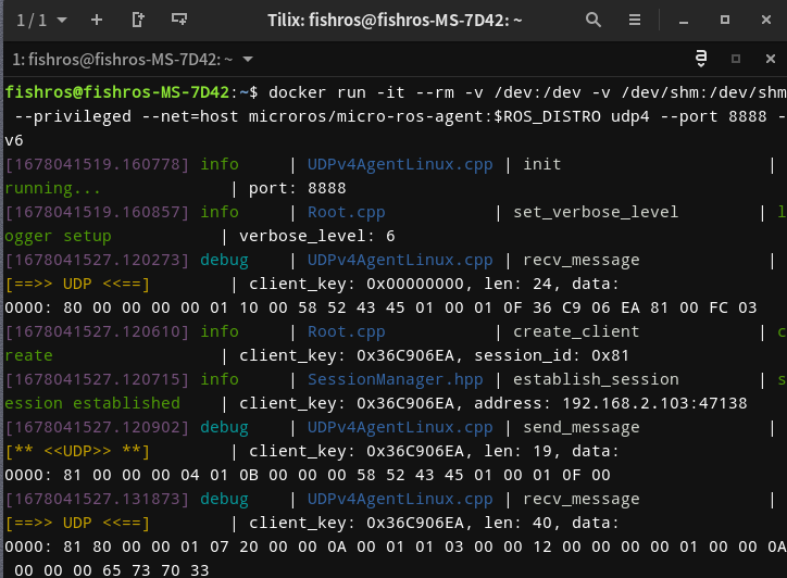
看到连接建立表示通信成功,接着用ros2 topic list
ros2 topic list
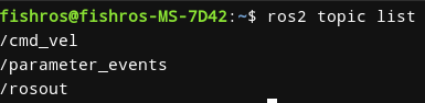
看到/cmd_vel表示正常,接着我们使用teleop_twist_keyboard进行键盘控制
ros2 run teleop_twist_keyboard teleop_twist_keyboard
随便发送一个指令,打开串口,观察打印
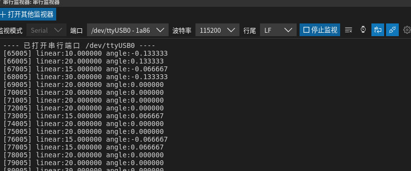
速度一直在20左右徘徊,和我们设置的速度相同。
void Kinematics::kinematic_inverse(float linear_speed, float angular_speed, float &out_wheel1_speed, float &out_wheel2_speed)
{
    // 直接返回指定速度20mm/s
    out_wheel1_speed = 20;
    out_wheel2_speed = 20;
}
四、扩展-Git初体验
4.1 Git使用简介
- 安装 Git:如果你的系统中没有 Git,可以通过以下命令进行安装:
sudo apt update
sudo apt install git
- 配置 Git:在使用 Git 之前,你需要设置用户名和邮箱地址,这样 Git 才能正确地记录你的提交信息。使用以下命令配置 Git:
arduino
git config --global user.name "Your Name"
git config --global user.email "youremail@example.com"
将 "Your Name" 替换为你的姓名,"youremail@example.com" 替换为你的邮箱地址。
创建一个 Git 仓库:如果你要将一个现有的项目纳入 Git 的版本控制下,可以使用以下命令将其转化为一个 Git 仓库:
cd /path/to/your/project
git init
- 将文件添加到 Git 仓库:使用以下命令将文件添加到 Git 仓库:
git add filename
其中,"filename" 是要添加到 Git 仓库中的文件名。如果你要将所有文件添加到 Git 仓库中,可以使用以下命令:
git add .
- 提交更改:使用以下命令将文件的更改提交到 Git 仓库中:
git commit -m "commit message"
其中,"commit message" 是提交信息,需要用简短的文字描述本次提交的更改内容。
4.2 提交本节代码
根据上面的介绍我们可以使用git来将这一节的代码保存
安装
sudo apt install git
初始化仓库,配置邮箱和用户名
cd fishbot_motion_control_microros
git init
提交本次所有代码
git add .
git commit -m "feat(16.12):完成运动学正解"
git log
13.目标速度控制-运动学逆解
上一节我们推导并在代码中实现了运动学正解,本节我们来学习下运动学逆解,实现给定线速度和角速度,计算出轮子达到怎样的转速才能达到这个速度。
一、逆解推导
我们直接用正解结果进行求逆解即可。
所以有
二、编写代码
继续在上一节中的代码Kinematics.cpp中完善即可。
void Kinematics::kinematic_inverse(float linear_speed, float angular_speed, float &out_wheel1_speed, float &out_wheel2_speed)
{
    out_wheel1_speed =
        linear_speed - (angular_speed * wheel_distance_) / 2.0;
    out_wheel2_speed =
        linear_speed + (angular_speed * wheel_distance_) / 2.0;
}
三、下载测试
下载代码,运行agent,点击RST按键。
sudo docker run -it --rm -v /dev:/dev -v /dev/shm:/dev/shm --privileged --net=host microros/micro-ros-agent:$ROS_DISTRO udp4 --port 8888 -v6
看到连接建立表示通信成功,接着用ros2 topic list
ros2 topic list
看到/cmd_vel表示正常,接着我们使用teleop_twist_keyboard进行键盘控制
ros2 run teleop_twist_keyboard teleop_twist_keyboard
先调整下速度,降低到0.05左右(50cm/s),然后使用i\j\j\k\,测试。
四、总结
没啥好说的,记得提交下代码
git commit -m "feat(13.13):完成运动学逆解"
代码提交也是有规范的,我们一起来学习下:https://fishros.org.cn/forum/topic/390
我们采用用的比较多的Angular 规范
git commit -m "<type>(<scope>): <subject>"
其中 type(必选)、scope(可选)和 subject(必选)
Type
- feat:新功能(feature)。
- fix/to:修复bug,可以是QA发现的BUG,也可以是研发自己发现的BUG。
- fix:产生diff并自动修复此问题。适合于一次提交直接修复问题
- to:只产生diff不自动修复此问题。适合于多次提交。最终修复问题提交时使用fix
- docs:文档(documentation)。
- style:格式(不影响代码运行的变动)。
- refactor:重构(即不是新增功能,也不是修改bug的代码变动)。
- perf:优化相关,比如提升性能、体验。
- test:增加测试。
- chore:构建过程或辅助工具的变动。
- revert:回滚到上一个版本。
- merge:代码合并。
- sync:同步主线或分支的Bug。
scope(可选)
scope用于说明 commit 影响的范围,比如电机控制层、通信层等等,视项目不同而不同。
例如在FishBot嵌入式中,可以是motors,uart等。如果你的修改影响了不止一个scope,你可以使用*代替。
subject(必选)
subject是commit目的的简短描述,不超过50个字符。
结尾不加句号或其他标点符号。
举个例子 给FishBot增加了oled支持
git commit -m "feat(13.13):完成运动学逆解"